CA-320 & CA-321 Legacy Compass Correction System
Compass Calibration for All Aircraft Types
Fixed Wing Operations
Rotor Wing Operations
Simple and accurate compass calibration
Easy to Operate
Unsurpassed Accuracy
Saves Time and Money
Revolutionary, New, Portable Magnetic Standard For Compass Calibration
This stand-alone, portable, magnetic measurement standard replaces the need for a compass rose, master sight compass, surveyor transit devices and complex specialized equipment – all imprecise methods. The current time-consuming, labor intensive, costly process of aligning aircraft heading systems has been replaced by technology that matches the modern cockpit environment.
Developed for the aerospace industry, its benefits apply to marine, military and other compass calibration needs.
CA-320 – 0.5” resolution
CA-321 – 0.1” resolution
How it Works
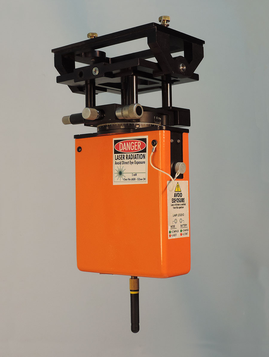
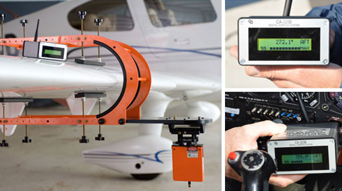
CA-320 & CA-321 uses state-of-the-art magneto resistive sensors to sense the Earth’s magnetic field in three dimensions. An integral laser provides for easy and accurate alignment with the longitudinal axis of the aircraft, vehicle or vessel being tested.
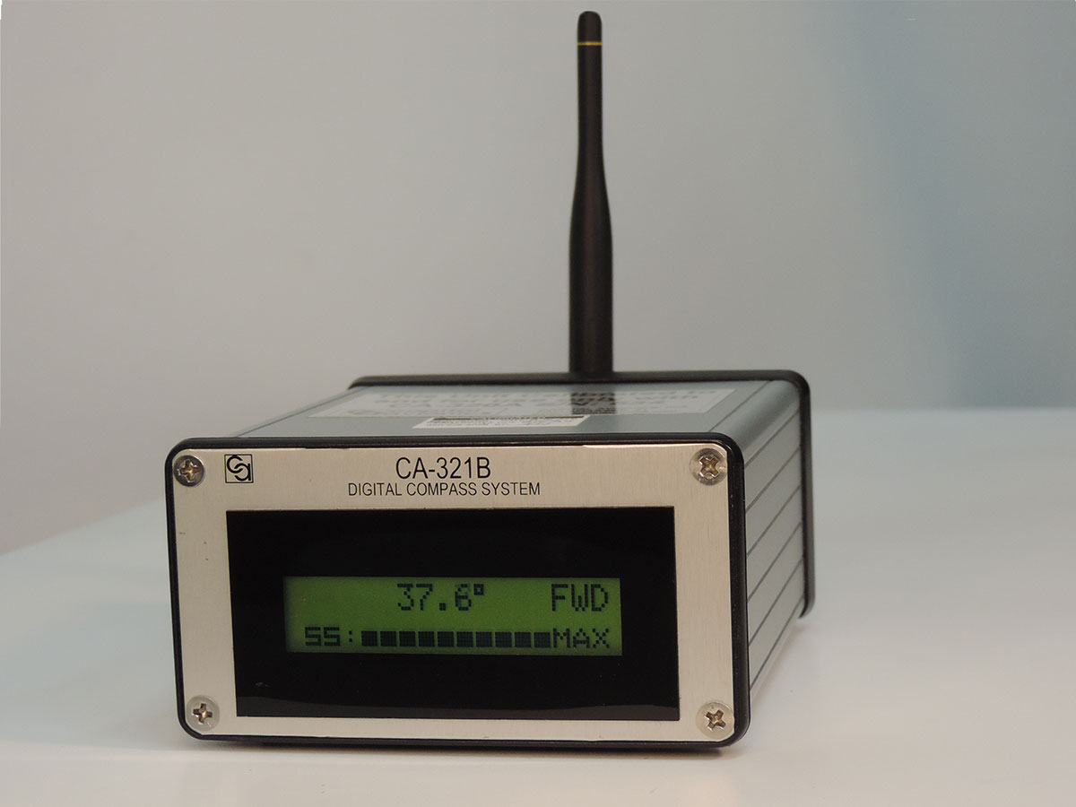
Finally, the precision heading measured is transmitted to a portable receiver giving the maintenance personnel the data in real time, where they need it.

Advantages
The Current Standard Was Written In The 1960s
Current heading systems are calibrated using MIL-STD 765A as a foundation document. MIL-STD 765A was originally written in the 1960s and has been revised from time to time to reflect changes in accepted procedures but still relies upon 1960s technology. This includes the use of compass roses, master site compasses, transit based systems referencing distant objects and electronic methods compliant with MIL-C-26524 (the latter requires the removal of the magnetic transmitter from the aircraft).
All of the methods described in this standard, except for the site compass, require the use of terrestrial based reference points, which may be difficult to locate under adverse weather conditions or at night. The master site compass is inherently inaccurate due to the resolution of the display and sensing device (suspended bar magnet).
The CA-320 & CA-321 Legacy
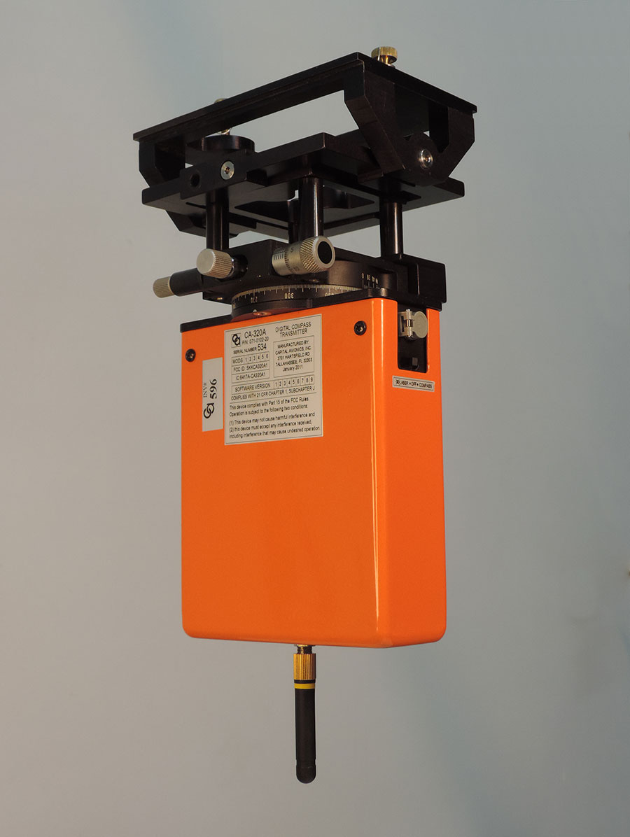
The CA-320A & CA-321A Sensor is easily aligned with the longitudinal axis of the aircraft and the digital heading is presented to the technician where the adjustments take place. No interpretation or special skills are needed for precise measurement.
Certifications
The CA-320 and CA-321 have the following certifications:
- Transmitter FCC Part 15 certified
- Class IIIA Laser FDA certified
- FAA accepted as a replacement for compass roses, master compasses, etc.
Components
The CA-320 is made up of the following components:
| CA-320A Transmitter | 071-0102-20 (0.5 degree) |
| CA-320B Receiver | 071-0104-20 (0.5 degree) |
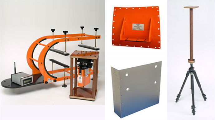
| CA-320C Wing Mount | 071-0105-00 |
| Chargers | 071-0106-00 |
| Tripod | 071-0044-00 |
The CA-321 is made up of the following components:
| CA-321A Transmitter | 071-0102-51 (0.1 degree) |
| CA-321B Receiver | 071-0104-51 (0.1 degree) |
| CA-320C Wing Mount Custom Adapter Mounts | 071-0105-00 071-0105-XX |
| Chargers | 071-0106-00 |
| Tripod | 071-0044-00 |
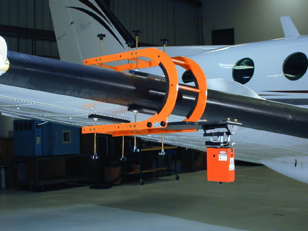
Fixed Wing Operation
For FIXED WING AIRCRAFT
the CA-320C general purpose wing mount adapter may be used.
First, the magnetic heading of the aircraft is determined by aiming the CA-320A’s integral laser along easily identified reference points. One common method is to mount the CA-320A atop a tripod and align the laser beam between the nose of the aircraft, the pilot and co-pilot windshields, antennas and/or seams of the aircraft’s skin.
An alternative method, for larger aircraft, is to aim the laser beam from the rear of the aircraft which is then aligned with antennas and/or other longitudinal axis reference points.
Having aligned the laser, the CA-320A function switch is set to COMPASS and the magnetic heading read on the CA-320B.
The CA-320C Wing Mount is placed onto the wing at a location determined to have little magnetic interference and secured. Next, the CA-320A is attached to the CA-320C and a quality test performed which verifies the state of the local magnetic field. Lastly, the CA-320A is adjusted so that the CA-320B reads the heading established by the laser alignment procedure previously performed. The technician is now ready to test and align the magnetic transmitter based compass systems.
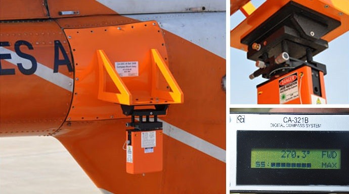
Rotor Wing Operation
For ROTORWING AIRCRAFT
or where high precision is required, airframe specific adapters and alignment templates are used.
First, an adapter is mounted onto the fuselage and the CA-320A or CA-321A attached and secured to it. A quality test is performed which verifies the state of the local magnetic field.
Next, the CA-320A or CA-321A laser is aligned with the Laser Template, which has been placed at a specified datum point on the fuselage. The CA-320A or CA-321A is then secured to prevent further movement and the function switch is set to COMPASS. The technician may now read magnetic headings on the CA-320B or CA-321B.
Applications
Developed originally for the aerospace industry, the technology is now being implemented in marine and military applications and can be adapted for any vehicle which requires accurate compass calibration.
Currently In Use Globally:
- Air Freight Operators
- Airlines
- Maintenance Repair Organizations
- Aircraft Manufacturers
- Military Aircraft Maintenance Support