Adapters
The CA-320/420 Digital Compass is mounted onto the aircraft and aligned with the longitudinal axis with the integral laser. It then transmits the aircraft heading to the receiver for the technician’s use.
There are two methods of aligning the sensor to the longitudinal axis. The methods differ in the accuracy required for the test.
The most common procedure is to place the compass on its tripod either in the front or rear of the aircraft. Then use the laser to align the compass with the aircraft centerline and read the heading presented on the digital display. This procedure provides best accuracy for compasses with 0.5° resolution.
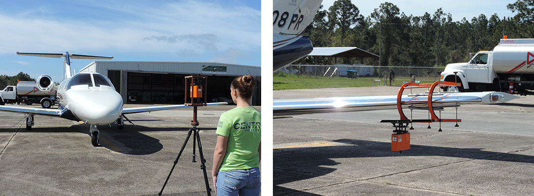
The sensor is then removed from the tripod and installed into the wing mount adapter, typically placed and secured near one wing tip. The sensor is then adjusted as necessary to match the heading found previously. From this point, the sensor is aligned with the aircraft and it may be pulled in a circle for heading tests.
Note that the aircraft engines are not started but power is supplied through external power, APUs or battery. For wet compass tests, one heading system becomes the master heading reference, with charted errors, and the engine(s) are then started and all test performed in the typical flight configuration.
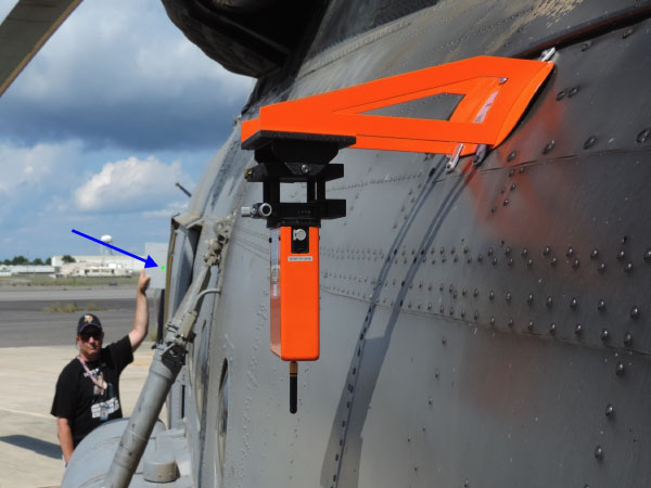
The second method of sensor alignment is used when highest accuracy is required. A unique procedure is written for a given airframe where the sensor location is specified. The laser is directed at a specified target which results in a heading correspondence between the sensor and aircraft of 0.1° or less.
The location of the sensor mount and laser target will depend on the airframe size and type, whether fixed-wing or rotorcraft. Examples below:
Elevator Mount
Fuselage Mount
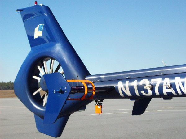
Vertical Stabilizer Mount
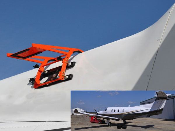
Large Aircraft Mount
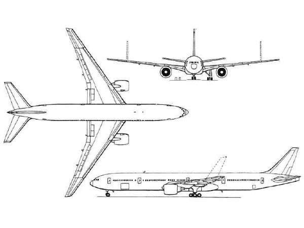
For large aircraft, the sensor may be mounted on a wing or horizontal stabilizer and aligned to a reference point on the aircraft.